|
History notes (Part 2)
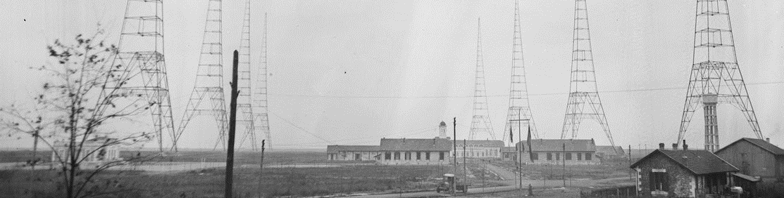
The buildings
The
station site includes in addition to the main building a
general warehouse, techninal building, restaurant
building, coal storage and locomotive
garage, personnel buildings (4), school,
Station
chief house ("the white house"), energy station, water
reservoir, garage, gas, pumps room, wood warehouse.
The main building is 76m long, 16m wide and 11m
high. It is divided into five
machines-rooms. The railway enters in it. More
rooms were added after 1938.
When building the parts of main building close
to radio equipment, no metal piece
was used (including for doors on whatever.
nuts,
door handles ... etc) or would be grounded to
avoid heating.
After 1938 a new room was built for new high
power lamp transmitter (callsign FYP).
And
in 1939 another one was built for lamp-tx shortwave
transmitters.
During
1939
was built a new cooling water reservoir and new pumps rooms.
The
water temperature would be at 25 C in all seasons (dissipating
about
100 kW) and staff could swim in it ,although
not
officially autorised.
The antenna
The antenna is made of 16 horizontal wires
carried by the eight 250m towers
(four towers on each side). The area of this horizontal
part is 400 meters x 1200 meters. Then
ten wires go down vertically into the main building to
the antenna coil. This vertical part is actually the active
part
of the antenna
The antenna coil is 5 to 6 meters high and same
diameter. With the horizontal
capacitive part and the ground, the coil constitute
the
tuned circuit.
Wavelenghts
are
between 19150 meters to 23450 meters.
The gound system was first a copper plate with
an area of 200 square meters burried
at 50 centimeters and connected to
100 vertical 14-meters-long copper tubes into the ground.
Then
was added a network of 60 kilometers of copper wire burried
under
the antenna. (you still find some today in the ground)
The transmitter
The spark transmitter : 1920 to 1923
It
is built by FEDERAL TELEGRAPH Co.. There are two
transmitters in Croix d'Hins, one is a
backup. Normal spark power is 1000
kW and the yield to change DC to AC
is about 50% leading to 500 kW HF. The
spark is fed under 1250 volts and 800 Amperes. Its
weight is 80 tons, 70 tons being for the magnetic circuit.
That huge cover is 2.8 meters high. Its primary
coils is in series with the spark and
has the 800 Amperes. It is immerged into oil cooled by
the water circuit, pumps and external reservoir. The
magnetic field reaches 17000 Gauss. Visitor's
watches
would often be damaged. Heavy metal pieces lifted
more
than one meter from the cover would not fall down
but would stick to it.
Spark
anode
is a copper tube one centimeter diameter cooled by
water. Cathode is made of carbon, 4 centimeters diameter and
50 centimeters initial length. It is replaced every 24
hours.
It
is rotating for a regular erosion. The
spark chamber has an atmosphere of alcohol and petroleum (falling
drop
by drop) to improve efficiency. (20 liters / 24H)
The 1250 volts / 800 amps are obtained from a
1000 kW converter group working under 2200
volts AC coming from the energy building final
transformer.
Stabilized spark results in one frequency being
transmitted. Morse modulation is obtained
by frequency shift. The frequency shift is
obtained by short-circuiting one loop
in the antenna coil (actually not one of the real loops
but 78 smaller loops simultaneously short-circuited. The
78 breakers have silver terminals. They are fed by a 20 kW
generator.
The spark transmitter callsign is : LY
Up to 27 harmonics have been found to be
generated and these transmitters are
causing troubles to others and to the
newly introduced radio broadcasting.
From 1923, spark transmitter is kept as backup
but replaced by new HF generator, type
Bethenod-Latour. (patent by Marius Latour,
1917)
The
output power is 500 kW with a 84 percent yield. Its
single HF output wavelength is 19150 meters. Its
callsign is : FYL
Return to
first part
Go to Part 3
Other
references :(thanks Al Heiden, Don
Kimberlin)
2020 Updated reference links http://f5nsl.free.fr/lafayette-radio-station-documents.html
- See a description of the station
from an online version of "History of communications-Electronics
in the United States Navy".
at : http://www.angelfire.com/nc2/whitetho/1963hw20.htm#20sec6
(local
copy)
The History of NSS, Annapolis,
Maryland [n.a.]
The Telegraph Office :
http://www.metronet.com/~nmcewen/Federal_Telegraph_Relay.html
[n.a.]
George T. Royden oral history :
http://www.ieee.org/organizations/history_center/oral_histories/transcripts/royden10.html
[n.a.]
The Passing of A Pioneer :
http://antiqueradios.com/pioneer.shtml [n.a.]
Page by Pierre Dessapt :
http://perso.club-internet.fr/dspt [n.a.]
Jurassic Telecommunication :
http://www.oldradio.com/archives/jurassic/
Don Kimberlin's page :
http://members.fortunecity.com/donkimberlin [n.a.]
Informations or documents about Lafayette
Station are welcome at : eric.tiffon@freesbee.fr
Main source : Leaflet by A Nicolazzi, Direction des
télécommunications du réseau international "Croix d'Hins
ou historique de "Bordeaux - Lafayette" , 1977
Aug 2000 - 80th anniversary
|